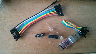
Inverter Circuit with an 74HC04 Chip
Lately,
you'll have realised I'm writing about electronics like UART
connections of an Orange router or
how to see the booting
process of broadband routers.
Therefore, I have used words like
multimeter, oscilloscopio, ground, volts, etc in previous posts.
However, this time, I want to go beyond and I have bought a couple of
inverters with some leds and a breadboard
to make some experimental circuits. At
first, in this post, we'll see how the 74HC04 inverter works and how
to test it.
An
inverter is a chip that it's be able to change the logic state of an
input to the opposite state. For example, if the input is a HIGH
logic signal, the output is a LOW logic signal, and if the input is a
LOW logic signal, the output is a HIGH logic signal. This
is a basic and necessary chip when we want the opposite state of an
input state.
The
74HC04 hex inverter chip has 6 gates where the logic signal output by
an inverter gate is the opposite of the logic signal fed into the
gate. In addition, we can see in the 74HC04
datasheet
that the A's of each gate are the inputs
and the Y's of each gate are the outputs, meaning Y
is the opposite logic signal of A.
Once
we know how it works, it's time to test it. I've built a small
circuit with an inverter chip and two leds. One led is connected to
the input (A) and the second led is connected to the output (Y) with
the goal of testing the first gate. Therefore, one led is connected
between the first pin (A) and the seventh pin (GND) and the other led
is connected between the second pin (Y) and the seventh pin (GND).
I've also fed the inverter chip through the
14 pin with 5 volts and I've connected it to the ground as well
through the seventh pin. What should there
be the result? The led number 1 turned off because it's not being fed
and the led number 2 turned on because the opposite of a LOW logic
signal in the first pin is a HIGH logic signal for the second pin,
where the led number 2 is connected. It is
represented in the next diagram:
 |
| Led 1 turned off and Led 2 turned on |
On
the other hand, if the first pin (A) has a
HIGH logic signal with 5V, we'll see that the led number 1 is turned
on while the led number 2 is turned off. Why? Because the led number
1 is being fed and the led number 2 has the opposite, not being fed,
as a result, turned off. It is represented
in the next diagram:
 |
| Led 1 turned on and Led 2 turned off |
This
is an easy way to test each gate of our inverter chips and especially
to understand how it works. Next, we have a video I recorded.
Regards my
friends, drop me a line with the first thing you are thinking.


Commentaires
Enregistrer un commentaire